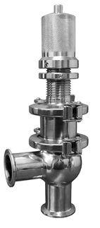
Tri-Clamp® Sanitary Pressure Relief Valves
Pazzini 900 Series
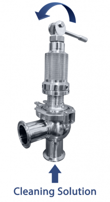

CIP Pneumatic Override
STARTING AT $788.24CIP Manual Override
STARTING AT $774.12New Model!
STARTING AT $797.65")

Note: All V2B Vacuum/Vent Breaker Gaskets require the use of a retainer ring.
APPLICATION
Pressure Relief valve is a hygienic manually adjustable valve used in the food, beverage and processing industry applications where over pressure must be discharged in order to avoid damage to plant and / or personnel
Watch Video
Features:
- Made in SS316L / wetted surfaces
- Manually adjustable from 10 to 150 psi
- The specific pressure is set by adjusting the spring pressure nut.
- Seat gasket replacement in less than 10 minutes without removing the valve from the line and no tools required.
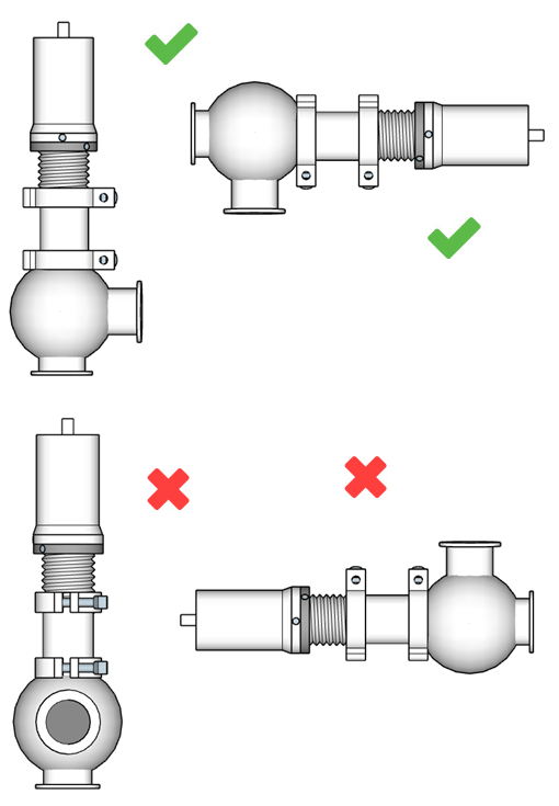
“Avoid dead legs”
The critical factor in a hygienic piping system is design without dead legs to avoid the possibility of microorganism growth.
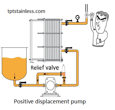
When you install a relief valve connected to the suction side of the pump (Bypass) a dead leg is formed.
Dead legs are sections that are not washed through in the normal cleaning path.
To avoid this situation our valves are pneumatic/manual operated in order to open the valve during the clean-in-place (CIP) .
WORKING PRINCIPLE
If the discharge valve of a sanitary centrifugal pump is closed and there is no other flow path available to the pump, the impeller will increase the temperature of the liquid (due to friction) in the pump to the point that it will flash to vapor. If the pump is run in this condition for a significant amount of time, it will become damaged.
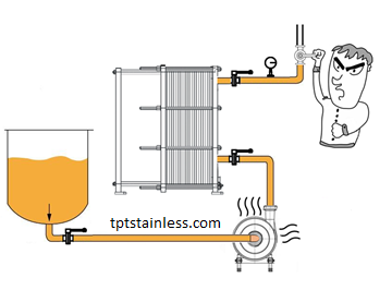
If you close a valve downstream of a positive displacement pump, pressure will build and at some point the weakest part of the system will fail. The pump, tube, clamps, hoses or others components will break causing catastrophic damages to the plant and/or personnel.
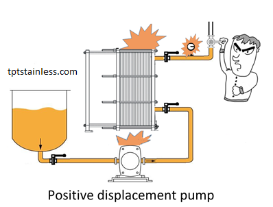
Pressure relief is a spring-loaded sanitary manually adjusted valve specifically designed to prevent risks and potential failure caused by pressure surges within the line. When the line pressure exceeds the limit set for the safety valve, the valve plug will lift and release the pressure through the side port. The valve will remain open until the line pressure decreases to a value lower than the set value.
SETTING THE RELIEF PRESSURE
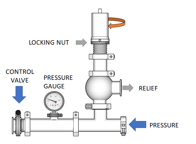
- Loosen the locking nut and start with the adjusting knob without any pressure applied to the internal spring.
- Close the control valve after the relief valve and then Turn on the pump or supply line. At this time, the fluid is flowing through the pressure relief valve.
- Turn the adjusting Knob clockwise, while checking the pressure gauge and stop turning the adjusting knob when setting pressure is reached. The relief valve close when the supply pressure is equal to the setting pressure. If supply pressure is greater than the setting pressure, fluid should flow through the valve.
- Turn off the supply pressure and open the control valve to depressurize the system and then close the control valve and turn on the supply pressure to check the desired setting pressure. If system requires an increase or decrease in pressure adjust the knob to requiring setting:
To increase the pressure turn the knob clockwise
To decrease the pressure turn the knob counter-clockwise. - Repeat step 4 a couple of times and then tighten the locking nut.
INSTALLATION